There are two parts to this. 1) you need to give the robot the tool, and 2) you need to tell it what it is. We will be working in Rhino and in Python, respectively.
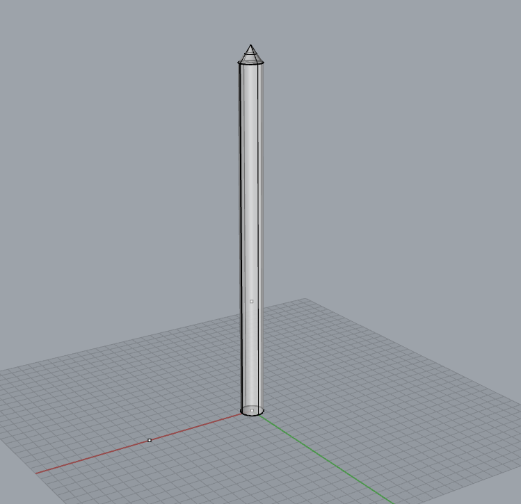
We are going to start by taking an existing tool and converting it into our tool, the Pointy Cylinder. You can find the existing tools in the SMT/Resources/Geometry folder.


- The Orientation Points
- The Tool Changer
- The Tool
- The Tool Tip (TCP)

The Orientation Points and the TCP are the only parts of this model that sMT needs. The Tool and Tool Changer are what will appear when you simulate your program and are, presumably, how you will define your TCP.
The TCP is the very end of your tool, be it the nozzle of the extruder, the focal point of the laser, or the tip of your marker. It is a set of (x,y,z,a,b,c) coordinates. This point will follow the tool path precisely.
The Tool is a model of your tool. It is up to you the level of detail you want to go with this, as it will only be visible in sMT simulations. The part of this that should be precise is the tip of the tool, as that will be how you define your TCP.
The Tool Changer is what will allow us to easily switch between different tools in the future. The tools have the female end, and the robot the male end. When the male Tool Changer is attached to the robot, you will have to attach your tools to the female one in order to get them on the robot. As this has not yet happened, it is not important to us at this time.
The Orientation Points are how sMT knows the position and orientation of your tool. They are named <toolname>_UofM_Pt00, <toolname>_UofM_Pt01, and <toolname>_UofM_Pt02. They are located at the Origin, the Z axis, and the X axis, respectively. They must be named correctly in order for the tool to be read by sMT. sMT pulls a vector from 00 to 01 and another from 00 to 02, so they need not be at any specific distance, simply along the correct axis. A good rule of thumb is not to change or move anything unless you have to, however.
You can now delete any existing geometry you do not need, except for the Orientation Points. Rename these to match your file and tool name. You can rename objects at the top of the properties panel. Rename the layer that all the objects are on to match as well.


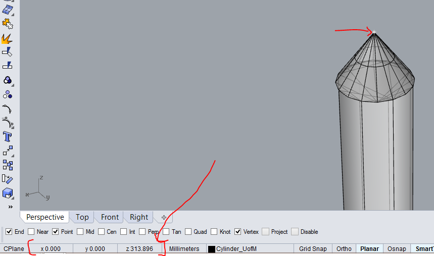
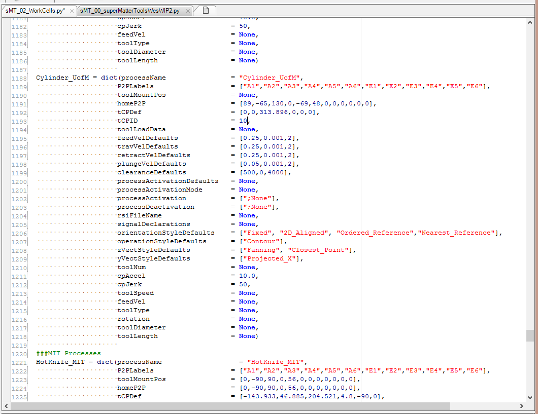
Next, locate your TCP's coordinates in your Rhino model, either a) by teaching the tool to the robot like we did for the last assignment and getting the coordinates from there, OR b) by snapping to it in your incredibly precise model and reading the coordinates from the bottom right corner of the screen. Take note of these as you will need them shortly. Convention dictates putting a point at your TCP, but it's not strictly necessary.
Now we teach the tool to sMT. Open up the RhinoPython editor by typing in EditPythonScript (this should be familiar). This time, instead of opening up the usual sMT_00 file, we will be opening sMT_02_WorkCells. The following will involve editing variables in the code, but don't worry, no knowledge of code is in any way required.
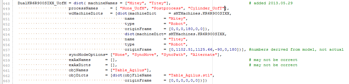
First, we will edit the WorkCell Definition Dictionary. The Dictionary starts on line 355, but the Dictionary Definition we want to edit is for the Agilus Workcell. It is found at line 448. We need to include your tool as an option in the Process drop down menu. On line 449, after "Posprocess" and before the square bracket, type in a comma (,), a space ( ) and the name of your tool (<toolname>_UofM) inside quotations ("). It should look like this. Save the file.

Startup -> Calibrate -> Tool -> Numeric input
Select tool no. 2 and change the x,y,z,a,b,c. Hit next to save. Should be good to go!
If there are any questions, see you guys at Office Hours.
Peace!
No comments:
Post a Comment